| Jump to:
|
NOTE: This research was a collaboration between Dr Neil Yager of AICBT Ltd and Dr Ted Dunstone of Biometix. If you are interested in fully assembled test kits, commercial support, or biometric vulnerabilities, please contact research@biometix.com. All code and design on this page is open source and freely available for you to use, redistribute, and/or modify as you wish. |
Biometric vulnerabilities
Almost all face recognition systems have a glaring vulnerability – silicone masks like this one:
 are treated as real faces. Furthermore, people have robbed banks and deceived immigration while wearing latex masks, which are becoming increasingly sophisticated and readily available. I bought this low-end mask:
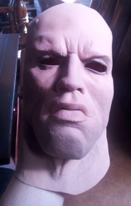 at a London costume shop for about £30. The salesman told me they get contacted by the Metropolitan Police every few weeks about someone who has committed a crime while wearing the mask. The police actually go around to all the shops and search through the sales receipts (remember: pay with cash).
In 2009 I wrote a book with Ted Dunstone, and we included a chapter on biometric vulnerabilities. We predicted that as recognition systems become more common, people will start looking for new ways to get around them. We recommended that vendors stop focusing purely on matching accuracy for authentic presentations, but also develop technology for liveness and spoof detection. Unfortunately, it is a problem that has been largely ignored, as witnessed by the recent iPhone 5s fingerprint scanner attack. Some commercial face recognition systems can be spoofed with a much easier presentation attack – simply hold up a photo or video clip (e.g. on an iPad) of an enrolled person to gain access using their identity.
As far as I know, there are no products available that specifically address this problem. I thought it would be interesting to see if a simple spoof detection system could be developed using inexpensive components and open-source software.
Disguise Detection
It is difficult to detect masks using only information from the visible spectrum. However, in the far infrared (IR) spectrum real faces have a distinctive heat signature:
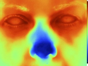 The surface temperature of a mask is closer to the ambient temperature, and the heat distribution is more uniform. It would be a challenge to create a mask that appears human-like in both the visible wavelengths and the far IR.
Unfortunately, high-resolution thermal cameras (like the one used for the image above) are very expensive – anywhere from $5,000 to $50,000. Our idea was to use multispectral imaging: combine a high-resolution visible wavelength camera with a low-resolution IR sensor. The underlying concept is simple. A subject must have something that looks like a face, and the temperature of this face-like object must be consistent with that of live human skin. It’s not hard to think of ways around this, but this relatively simple system can help protect against the easiest and most common spoofs.
Assembling the detection unit
1. What you’ll need
- Raspberry Pi: This is the perfect computer for this project due to its low cost, low power requirements, and active community.
- IR sensor: There are a few options available. Panasonic makes the Grid-EYE. We used the Melexis MLX90620, which has a resolution of 16×4. The advantage of this sensor is that it is cheap, and there is some open-source code available (see below). RoBoard has built a convenient MLX90620 module that can be hooked up directly to a controller. It’s a little more expensive, but it saved me from soldering a few bits together.
- Arduino: I used a Nano, but any board (such as the Uno) is fine.
- Camera: I used the official Raspberry Pi camera board. However, any RPi compatible webcam will do.
- Miscellaneous: A powered USB hub, wires & cables, LEDs, wifi dongle, enclosure, etc.
2. Connecting the IR sensor
I spent some time trying to get the Raspberry Pi and MLX90620 to talk to each other directly. I made a little progress, but ultimately I gave up as there seems to be an incompatibility between the RPi’s I2C library and some Melexis components (see this post for details). Connecting it to an Arduino was straightforward. Most of the info here applies to the MLX90620 and there are a few helpful threads on the official Arduino forum.
Here is the RoBoard’s IR component wired up to an Arduino Nano:
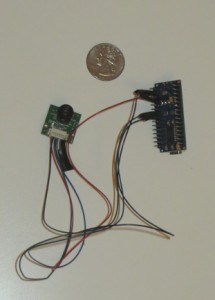 As you can see, both components are very small. Details about wiring can be found in the links above.
I used an Arduino sketch from SparkFun’s github repo to interface with the sensor using the I2C protocol. I made minor modifications to support serial communications, control an LED, and store the temperature values as bytes:
int LEDs[] = {4, 5, 6}; // the pins used for connecting the LED

// NOTE: I have not included all of the global variables and helper
//   functions here, as these are mostly unchanged. Please see
//   the SparkFun github repo link above for the rest of the source.

void setLED(int r, int g, int b)
{
  digitalWrite(LEDs[0], r);
  digitalWrite(LEDs[1], g);
  digitalWrite(LEDs[2], b);
}

void setup()
{
  Serial.begin(115200);

  // Init the I2C pins
  i2c_init();

  // Enable pull-ups
  PORTC = (1 << PORTC4) | (1 << PORTC5);
  delay(5); //Init procedure calls for a 5ms delay after power-on

  // Read the entire EEPROM
  read_EEPROM_MLX90620();

  // Configure the MLX sensor with the user's choice of refresh rate
  setConfiguration(refreshRate);

  // Calculate the current Tambient
  calculate_TA();

  // Init LED pins
  pinMode(LEDs[0], OUTPUT);
  pinMode(LEDs[1], OUTPUT);
  pinMode(LEDs[2], OUTPUT);
}

void loop()
{
  int incomingByte = 0;

  // Tambient changes more slowly than the pixel readings, so
  //  update TA only every X loops.
  if(loopCount++ == 20)   {
    // Calculate the new Tambient
    calculate_TA();

    // Check that the POR flag is not set
    if(checkConfig_MLX90620())
    {
      // Re-write the configuration bytes to the MLX
      setConfiguration(refreshRate);
    }
    loopCount = 0; // Reset count
  }

  // check if there has been any requests
  if (Serial.available() < 0) {
    char c = Serial.read();
    if (c == 'I') {
      // Get the 64 bytes of raw pixel data into the irData array
      readIR_MLX90620();

      // Run the calculations to fill the temperatures array
      calculate_TO();
      for (int i = 0 ; i < 64 ; i++)
      {
        Serial.write(temperatures[i]);
      }
      Serial.println('');
    }
    else if (c == 'R') { setLED(HIGH, LOW, LOW); }
    else if (c == 'G') { setLED(LOW, HIGH, LOW); }
    else if (c == 'B') { setLED(LOW, LOW, HIGH); }
    else if (c == 'x') { setLED(LOW, LOW, LOW); }
  }
  delay(50);
}
3. Connecting the Raspberry Pi and Ardunio
The next step is to establish communications between Raspberry Pi and Arduino. The Raspberry Pi needs to be able to issue two types of commands:
- A request to get the latest temperature values
- An instruction to change the LED color
There are three standard ways to setup the communications: over a serial USB cable, the serial pins on the GPIO, and using I2C (all three methods are discussed on this site). We’ll use the USB since it is reliable, trivial to setup, and can also be used to power the Arduino (although, make sure to use a powered USB hub).
4. Putting it in a box
I selected a box with dimensions: 11cm x 15cm x 7cm. I drilled three holes: one on the front for the camera, another on the front for the IR sensor, and one on the rear for the LED. The powered USB hub was the largest component – I needed to take it apart and cut it up so it would fit in my box:
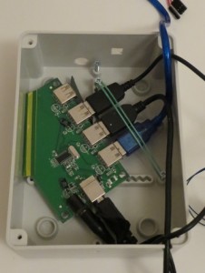 In the image above, you can see the holes for the camera and IR sensor. Here it is with everything packed in:
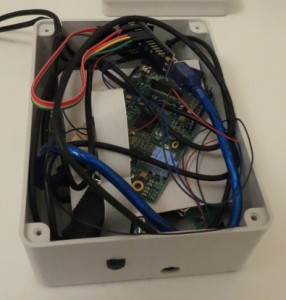 As you can see, there is quite a bit of empty space. However, the thick USB cables take up quite a bit of room, so I wasn’t able to use a smaller box. A properly designed enclosure would be much more compact.
Programming the Raspberry Pi
1. Installing libraries
A recommended, but optional, step is to overclock the Raspberry Pi using sudo raspi-config options. This will make everything run a little more quickly.
Next, we’ll make sure everything is up to date on the Raspberry Pi, and install a few libraries: PIL, numpy, scipy, OpenCV, pySerial, and various others. Execute the following in a shell:
sudo rpi-update
sudo apt-get update
sudo apt-get dist-upgrade
sudo apt-get install python-setuptools
sudo apt-get install git-core
sudo apt-get install cmake
sudo apt-get install python-numpy
sudo apt-get install python-scipy
sudo apt-get install python-imaging
sudo apt-get install libopencv-dev
sudo apt-get install python-opencv
sudo apt-get install python-serial
After these have finished (it may take a while), we install the latest scikit-image from the github repo:
sudo python -m easy_install cython
git clone http://github.com/scikit-image/scikit-image.git
cd scikit-image/
sudo python setup.py install
Run the following Python script to make sure everything has installed correctly, and the communications between the RPI and Arduino are working:
import serial
import time
import skimage
import cv2

# establish a connection with the Arduino
ser = serial.Serial('/dev/ttyUSB0', 115200)
time.sleep(1)
ser.setDTR(level=0)
time.sleep(1)

# test the LED
for color in ['R', 'G', 'B']:
    ser.write(color)
    time.sleep(1)
ser.write('x')

# get the most recent temperature readings
ser.write('I')
print ser.readline()
If everything is working, it will cycle through all the LED colors and print out the most recent temperature readings.
2. Capturing an image with the camera board
I used the official Rasberry Pi camera board for this project. The camera takes very high quality images. However, at the time of writing, the RPi foundation has not yet released an official Video4Linux driver for the camera, making it a little more difficult to use with Python. There are a few workarounds. Run the following Python script to capture an image, convert it to grayscale, and equalize the histogram:
import subprocess
import skimage
from skimage import io, exposure

def AcquireImage():
    fn = r'/run/shm/temp.jpg'
    proc = subprocess.Popen('raspistill -o %s -w 480 -h 320 -n -t 0'%(fn),
                            shell=True, stderr=subprocess.STDOUT)
    proc.wait()
    im = io.imread(fn, as_grey=True)
    im = exposure.equalize_hist(im)

    return skimage.img_as_ubyte(im)

im = AcquireImage()
io.imsave('image.jpg', im)
3. Aligning the IR sensor output with the optical image
Let’s take stock of what we have at this point:
- An Arduino that can (1) get temperature readings from the IR sensor, and (2) set the color of an LED
- A Raspberry Pi that can communicate with the Arduino, and can take photos
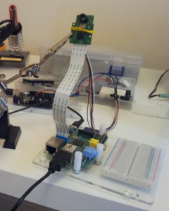
The picture below shows my testing setup. As you can see, see the camera and sensor are close to each other, and pointing in the same direction:
 What we need to do now is align the temperature values with the corresponding locations in the optical image. In other words, we need to apply a rotation, scale and translation to the 16×4 temperature array. At first I tried to tune the transformation parameters by hand, but this was inaccurate and cumbersome. Here is a high-level outline of the technique I used to automate the alignment stage:
- Fill a red coffee mug with very hot water
- Take 60 photos while moving the mug around the capture area. For each photo, record the corresponding IR array values.
- Find the location of the mug:
- Photo: Apply image processing techniques to find the middle of the red blob
- IR array: Double the size of the IR array (from 16×4 to 32×8), apply a Guassian filter, and find the location of the peak temperature. This is the (interpolated) location of the mug in the IR.
- Step 3 results in 60 pairs of correspondence points. Now find the rotation, scale and translation parameters that minimizes the (least-squares) distance between the points after the transform has been applied. This is a classic optimization problem, which can be solved using
scipy.optimize.minimize‘s implementation of Powell’s method.
Here is an example of the (smoothed) temperature readings aligned with the optical image:
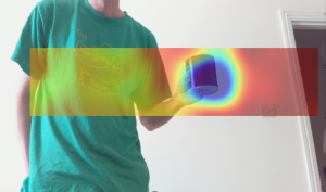 As you can see, since the mug is hot there is a clear peak in the IR spectrum. Note that there is a slight misalignment because the mug was in motion (towards me), and there is a lag in the temperature readings.
I found that the MLX90620 gives accurate/consistent temperature readings. My biggest complaint is that the aspect ratio (4:1) is inconvenient for this application. If it is oriented vertically, the unit will support a range of user heights, but the unit needs to be pointed directly at the subject. On the other hand, if it is oriented horizontally (as in the image above), there is more freedom for the subject to move side-to-side, and more than one person can be tracked at a time. However, there may be a problem if a subject is particularly short or tall. I ended up using the vertical orientation.
I would interested to test the Panasonic Grid-EYE, which also has 64 pixels, but they arranged in a square (8×8). I’m sure it won’t be long before some inexpensive higher resolutions IR components hit the market.
4. Liveness detection
We now have all the pieces in place to do liveness detection. The process is as follows:
- Take a photo
- Use OpenCV’s face finder to locate faces in the photo
- If the number of faces found is 0 or greater than 1, return to step 1
- Get the temperature array from the IR sensor
- Find the temperature of the face
- If the face temperature is less than an empirically determined threshold (e.g. 25° C):
- classify the face as a fake, and illuminate the red LED
- If the face temperature is greater than the threshold:
- classify the face as real, and illuminate the green LED
- Optional: save all results in JSON format, which will be used by the web server
Here is the code:
import numpy as np
import cv2
import subprocess
import os, sys, time
import serial
import json
import datetime
import skimage
from skimage import io, exposure, transform

FACE_TEMP_THRESH = 25
JSON_DIR = r'/home/pi/workspace/disguise/data'
IMAGE_DIR = r'[path to web2py application folder]/static/images/'
FACE_CASCADE_FN = r'[OpenCV cascades]/haarcascade_frontalface_alt.xml'

# IR registration parameters
ROTATION = 0
SCALE = (34.7, 34.8)
TRANSLATION = (70, 86)

# initialize communication with Andriod
ser = serial.Serial('/dev/ttyUSB0', 115200)
time.sleep(1)
ser.setDTR(level=0)
time.sleep(1)
ser.write('B')
time.sleep(1)

def AcquireImage():
    fn = r'/run/shm/temp.jpg';
    proc = subprocess.Popen('raspistill -o %s -w 480 -h 320 -n -t 0'%(fn),
                            shell=True, stderr=subprocess.STDOUT)
    proc.wait()
    im = io.imread(fn, as_grey=True)
    im = exposure.equalize_hist(im)

    return skimage.img_as_ubyte(im)

def MainLoop():
    # load the OpenCV face finder
    faceClassifier = cv2.CascadeClassifier(FACE_CASCADE_FN)
    file_count = 0

    while True:
        file_count += 1

        # clear the LED
        ser.write('x')

        # take a photo and look for a face
        im = AcquireImage()
        faceRects = faceClassifier.detectMultiScale(im,
                         1.2, 2, cv2.cv.CV_HAAR_SCALE_IMAGE)
        print 'Faces detected: %d' % (len(faceRects))
        if len(faceRects) != 1:
            # no faces found, so take a new photo
            continue

        # get face coordinates, and make sure the face
        #  isn't too far away
        x, y, w, h = faceRects[0]
        if w < 80:
            print 'Face too far: %d' % (w)
            continue

        # get the temperature array, and align with the image
        ser.write('I')
        ir_raw = ser.readline()
        ir = np.frombuffer(ir_raw.strip(), np.uint8).astype(np.float32)
        ir = ir.reshape((16, 4))[::-1, ::-1]

        # align the IR array with the image
        tform = transform.AffineTransform(scale=SCALE, rotation=ROTATION,
                                          translation=TRANSLATION)
        ir_aligned = transform.warp(ir, tform.inverse, mode='constant',
                                    output_shape=im.shape)

        # set the temperature of the face as the maximum
        #  in the face bounding box
        face_temp = ir_aligned[y:y+h, x:x+w].max()

        # create a dictionary to store the results
        results = {}
        results['timestamp'] = str(datetime.datetime.now())
        results['faces_found'] = str(len(faceRects))
        results['upper_left_x'] = str(x)
        results['upper_left_y'] = str(y)
        results['face_width'] = str(w)
        results['face_height'] = str(h)
        results['face_termperature'] = str(face_temp)
        results['disguise_detected'] = str(face_temp < FACE_TEMP_THRESH)
        results['ir_values'] = ','.join('%0.02f'%(f) for f in ir.flat)

        # determine face vs non-face based on temperature
        if face_temp < FACE_TEMP_THRESH:
            ser.write('G')
            time.sleep(5)
        else:
            ser.write('R')
            time.sleep(5)

        # save image in a place where the web server can display it
        fn = 'capture_%03d.jpg' % (file_count%100)
        results['optical_image_filename'] = fn
        io.imsave(os.path.join(IMAGE_DIR, fn), im)

        # save the results dictionary as a JSON file
        fn = os.path.join(JSON_DIR,'results_%03d.json' % (file_count%100))
        with open(fn, 'w') as f:
            f.write(json.dumps(results))

if __name__ == '__main__':
    MainLoop()
5. A web2py web interface
The final step is optional. For the device described so far, the only means of output is an LED indicator on the rear. However, in many situations it would be more convenient to monitor the results remotely through the web. web2py is an open source Python web framework that is perfect for this application. It is bundled with everything you need to quickly get an application up and running, including a web server, an administrative interface and an IDE (which is very convenient when doing headless RPi development).
To install web2py on a Raspberry Pi, execute the following from a terminal:
wget http://web2py.com/examples/static/web2py_src.zip
unzip web2py_src.zip
cd web2py
Note that in order to use the admin interface remotely, you will need to generate a self-signed SSL certificate. After you’ve done that, execute the following to start web2py:
sudo python web2py.py -i 0.0.0.0 -p 8000 -c server.crt -k server.key
Enter an admin password, visit https://[ip address of your RPi]:8000/, and you are ready to go. web2py can create a template application for you with a database backend, user authentication, etc. For our application, we created a controller than returns the most recent results as JSON:
import glob
import os
import json

JSON_DIR = r'/home/pi/workspace/disguise/data'

def index():
    # load most recent JSON file
    files = glob.glob(os.path.join(JSON_DIR, '*.json'))
    if len(files) == 0: return response.json([])
    files.sort(key=lambda x: os.path.getmtime(x))
    fn = files[-1]

    with open(fn) as f:
        return response.json(json.loads(f.read()))
On the client side, JavaScript polls for the latest results, and updates the display with the most recent capture image, face temperature, etc.
Demonstration videos
The following video demonstrates a few presentation attacks, as seen from the camera’s perspective. The first attack uses a printed cardboard mask (available online for a few dollars), and the second uses a video clip playing on a tablet. This demo was created using a webcam and PC, instead of the Raspberry Pi method outlined above. The results are the same but with a higher frame rate. red box=fake face, and green box=real face:
The following video shows the Raspberry Pi-based detector. It’s a little hard to see, but watch for the LED on the rear of the unit. Red LED=fake detected, and green LED=no fake detected:
Extensions, other applications and contact
This system is not foolproof. It’s not hard to think of ways to defeat it, but it’s also not hard to think of ways to improve it (e.g. detect a pulse using Eulerian Video Magnification). The main point is that if we are going to rely on biometric identification systems (e.g. for border control), we need to be aware of their limitations and look at ways to make them more secure.
There are many other potential uses for this box. Essentially, it is a combination of: (low cost hardware) + (open source software) + (computer vision) + (remote temperature sensing). Here are a few ideas:
- The same system can be used to detect people (or animals) with abnormally high or low body temperature. For example, detecting people with fever symptoms.
- Skin temperature may give insight into a computer user’s emotional state. For example, it may be able to detect frustration levels for user experience testing, or be integrated with online therapy systems.